OSI and TCP/IP Models in Practice
Use OSI and TCP/IP layers as practical reasoning tools for encapsulation, addressing, protocols, and troubleshooting.
Models organize network responsibilities
The OSI model separates communication into seven conceptual layers; TCP/IP groups real protocol responsibilities more broadly. Both help people name where a function occurs without claiming every implementation follows a perfect boundary.
Use the models as shared vocabulary. OSI commonly describes physical, data-link, network, transport, session, presentation, and application functions; TCP/IP usually groups link, internet, transport, and application responsibilities. Real operating systems and protocols cross conceptual borders, so arguments about a single “correct layer” are less useful than identifying the function, implementation, and evidence relevant to the problem.
Follow encapsulation through the path
Application data is represented, transported in segments or datagrams, addressed in packets, delivered in frames, and transmitted as signals. Each hop may change link-layer details while the end-to-end conversation retains other identifiers.
For a web request, DNS may first resolve a name, TCP or QUIC establishes transport behavior, IP routes packets, and a local link delivers frames. Routers replace link-layer framing at each hop; address translation or proxies can also change identifiers above that layer. Encapsulation explains why a packet capture at one point may show an IP address but not the original application identity, and why encryption can protect application content while leaving some transport metadata visible.
Map OSI to TCP IP pragmatically
Application protocols span the upper OSI layers, TCP and UDP provide transport, IP routes between networks, and link technologies handle local delivery. Use the mapping as a guide, not a rigid argument about labels.
HTTP, TLS, DNS, SMB, and authentication protocols may combine functions that OSI separates. TCP offers ordered byte delivery and connection state; UDP provides datagrams without the same transport guarantees; IP supplies addressing and routing; Ethernet or Wi-Fi handles local link delivery. Name the protocol and observed function in reports—for example, “the TLS handshake failed after TCP connected”—instead of relying only on “Layer 6 problem.”
Locate evidence at the right layer
Browsers, applications, operating systems, switches, routers, resolvers, firewalls, proxies, and sensors see different evidence. Passive DNS and WHOIS answer only some network questions and have their own vantage and time limits.
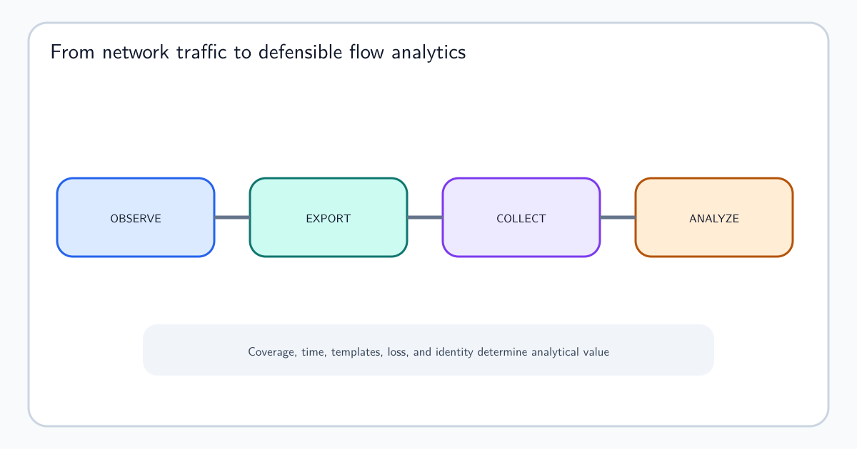
An endpoint can associate a socket with a process and user; a switch sees local frames; a router sees routed packets; a firewall may add policy outcomes; a proxy can see application requests; a resolver records DNS questions it receives. Routers and dedicated probes can also produce NetFlow and IPFIX records that summarize observed network and transport fields. Select evidence from the component authoritative for the fact. A firewall allow event does not prove the application completed a transaction, and a DNS answer does not prove a later connection used it.
Troubleshoot from symptoms
Start with the observed symptom, identify the responsible function, test the nearest boundary, and move layer by layer. Confirm names, addresses, routes, ports, sessions, encryption, and application responses without assuming the first failure explains the whole path.
For “the website is down,” first define user, device, network, name, time, and expected service. Test local connectivity, name resolution, route and reachability, transport establishment, TLS negotiation, HTTP response, and application behavior. Compare another client or vantage point carefully; success elsewhere narrows scope but does not prove the first path is healthy. Record commands, times, and outputs so the diagnosis is reproducible and changes can be verified.